Room 202-3, Building 30, No. 220 Xianggong Road, Xiangzhou District, Zhuhai City
08.00 AM-09.00 PM

Introduction
Gear reducers, often called gearboxes or gear reductions, are the unsung heroes of modern machinery. They convert the high-speed, low-torque output of an electric motor into the low-speed, high-torque motion that drives a conveyor belt, a robotic arm, or a wind turbine hub. From the standpoint of a manufacturer, choosing the right gear reducer is a multi-faceted task that blends mechanical insight with practical production concerns. In this article we’ll walk through the main selection points, outline the core calculation methods, and show how the latest trends in Industry 4.0—digital twins, real-time monitoring, and additive manufacturing—are reshaping gear design and production.
1. Core Selection Points
When the engineer sits down to pick a gear reducer, these are the decision anchors that guide the process:
| Point | Why It Matters | Typical Manufacturing Consideration | |-------|----------------|---------------------------------------| | Required torque & speed | Defines the gear ratio and physical size. | Larger gear ratios often lead to tighter tooth geometry, increasing the need for precise cutting tools. | | Efficiency target | Affects energy cost and thermal load. | Higher efficiency reduces heat, allowing use of lighter alloys and less heat‑treating energy. | | Load environment | Static vs. dynamic, shock loads, or continuous operation. | Shock-rated gearheads may require finite element analysis of tooth contact and extra brackets. | | Space constraints | Product package size, shaft positioning. | Compact gearboxes often employ helical or planetary gear trains which demand more accurate alignment during assembly. | | Life expectancy & reliability | Determines maintenance strategy and warranty. | Longer life needs higher fatigue strength, leading to tougher material choices and surface treatments. | | Cost & material | Balance between performance and budget. | Material selection impacts cutting tool wear, heat‑treatment costs, and overall cycle time. | | Maintenance ability | Torque limits, ease of gear change. | Modular designs with detachable gear stages can cut downtime dramatically. |
These “allocation points” set the stage for any design effort. A missing or mis‑judged factor can ripple through the entire production line, escalating cost or causing premature failure.
2. Fundamental Calculation Methods
The mechanical equations governing gear reducers are standardised under ISO 6336 and DIN 3960, but every manufacturer ultimately wants a quick mental check before handing the design to a CAD engineer. Below are the key formulas and the typical manufacturing checks that accompany them.
2.1. Gear Ratio and Module
Manufacturing check: smaller modules mean finer teeth that require higher‑precision cutting tools; larger modules enable lighter gears but reduce the maximum achievable torque.
2.2. Load per Tooth and Bending Strength
Normal load per tooth: ( Fn = \frac{T}{r \cdot Nt \cdot \eta} )
where ( T ) is torque, ( r ) the cylinder radius, ( N_t ) the number of teeth in mesh, and ( \eta ) the efficiency.
Bending strength criterion: ( \sigmab = \frac{Fn}{b \cdot m \cdot K} )
with ( b ) the face width, ( m ) the module, and ( K ) a shape factor from ISO tables.
Manufacturing check: if ( \sigma_b ) exceeds the material’s allowable bending stress, the gear assembly must be re‑designed – either by increasing face width or selecting a tougher alloy.
2.3. Fatigue Life (Wohler Curve)
The gear’s life expectancy is often estimated from the S-N curve:
( Nf = a \left( \frac{\sigma{\text{max}}}{\sigmay} \right)^{-b} )
where ( Nf ) is cycles to failure, ( a ) and ( b ) are material constants, and ( \sigma_y ) is yield stress.
Manufacturing check: for application‑driven fatigue requirements (e.g., 20 MW yr), the gear face width and heat‑treating parameters must be set to meet the target.
2.4. Contact Ratio and Backlash
Manufacturing check: a low contact ratio (approaching 1.0) is common in compact gearboxes but requires tighter machine tolerances to avoid load spikes.
3. Practical Manufacturing Considerations
Beyond formulas lie the real-world constraints that shape a gear’s final geometry:
| Constraint | Typical Manufacturing Impact | Industry 4.0 Leveraged Solution | |------------|-----------------------------|-----------------------------------| | Tool wear & geometry | Micro‑variation in tooth cuts changes load distribution. | Real‑time tool wear monitoring via machine‑vision can trigger adaptive feed rates. | | Heat treatment & surface finish | Inconsistent tempering can create “cold spots” that lead to cracking. | Digital twins model heat flow, informing the exact furnace schedule required for a uniform micro‑structure. | | Tolerances | Over‑tight tolerances inflate machining time. | Orthogonal machining strategies and 5‑axis robots reduce cycle time while maintaining precision. | | Assembly alignment | Misaligned gears cause bearing wear and noise. | AI‑based inspection systems detect deviations during pilot runs, allowing tight correction before full batch. | | Material sourcing | Variability in alloy composition influences bending strength. | Blockchain‑verified traceability ensures material data consistency across suppliers. |
An example: a conveyor belt drive requires 300 Nm torque at 86 rpm. Calculations show a module of 3 mm, 20 teeth on the driver, and 80 teeth on the driven gear. But if the manufacturing baseline uses a heat‑treatable alloy (AISI 1075), the face width must be increased from 15 mm to 18 mm to keep the bending stress below 30 MPa. Additive manufacturing of a ceramic‐coated gear case lowers maintenance, and the digital twin predicts a 15 % life gain over conventional steel gearboxes.
4. Digital Trends Shaping Gear Reduced Production
Industry 4.0 is no longer a buzzword; it’s a toolkit that unites simulation, data‑analytics, and smart manufacturing.
This convergence empowers manufacturers to offer tailor‑made gear reduction solutions at lower cost and shorter lead times while meeting the rigorous performance demands of, say, electric vehicles or renewable‑energy drive systems.
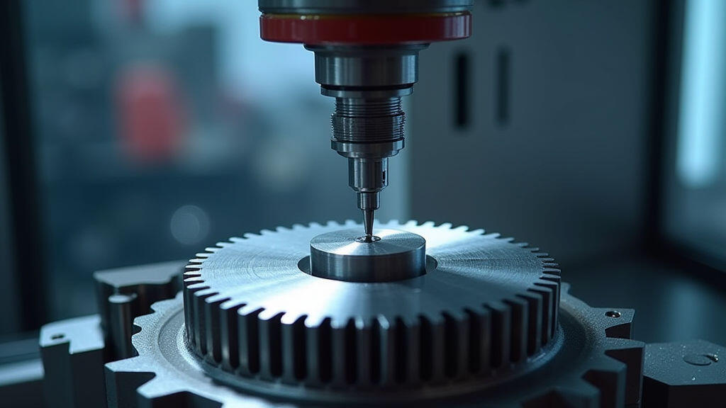
5. Illustrative Image Prompts

Conclusion
Choosing a gear reducer is a dance between mechanical theory, material science, and the realities of the shop floor. By anchoring decisions on the critical selection points—torque, speed, efficiency, space, and reliability—and validating them with proven calculation methods, manufacturers can design gearboxes that not only meet but exceed the performance expectations of their clients. The integration of Industry 4.0 technologies—real‑time data, digital twins, and smart tooling—further refines this process, enabling faster design iterations, higher quality, and lower life‑cycle costs. As the push for sustainable, AI‑driven manufacturing accelerates, gear reducers will continue to evolve from simple mechanical components into integral parts of intelligent, resilient production ecosystems.

Leave A Reply
Your email address will not be published. Required fiels are marked