Essential for Agricultural Machinery Automation Upgrades: A Guide to Gear Reducer Selection and Matching
2025-11-07
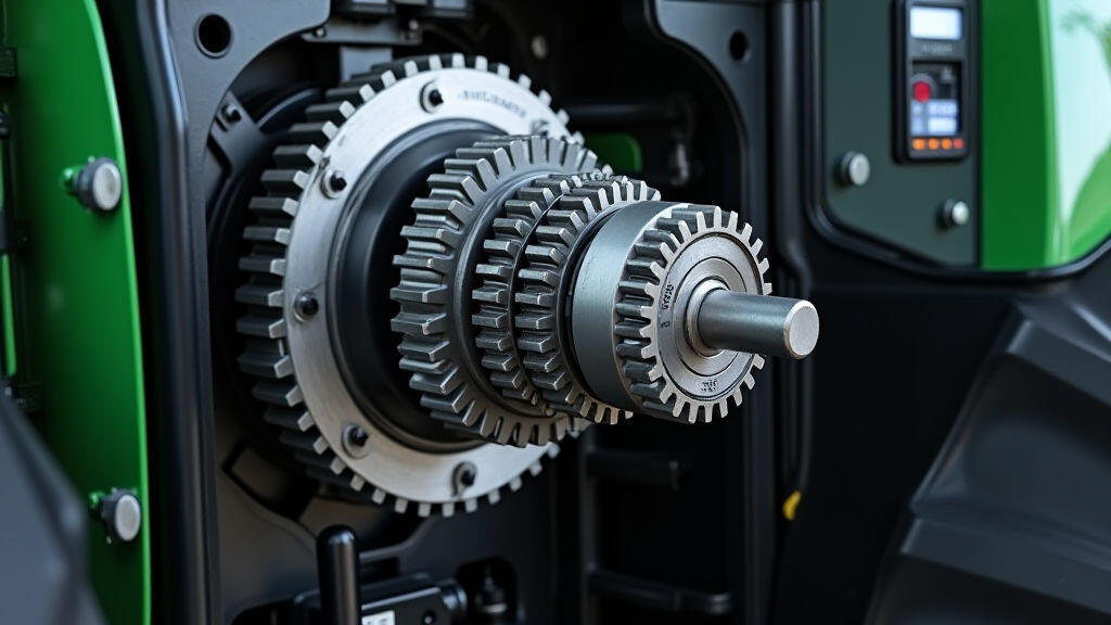
Why Gear Reducers Matter in Modern Farm Tech
In today’s fast‑moving agriculture, machines that once relied on simple, manual controls are increasingly being fitted with advanced automation – from GPS‑guided tractors to robotic harvesters. At the heart of any automated system that needs torque, speed, or precise positioning lies the gear reducer. These devices step down the high speed and low torque of an electric motor or hydraulic pump into the low speed and high torque needed by a tool or actuator. Choosing the right reducer is therefore critical for performance, reliability, and cost‑effectiveness.
The Basics: What Is a Gear Reducer?
A gear reducer transforms input power into output power by changing the speed and torque of a rotating shaft. It typically consists of: • – receives power from a motor or pump •
Key Factors to Consider When Picking a Reducer
Torque and Speed Requirements
Calculate the required output torque and speed for the specific farm task – whether it’s turning a tiller, operating a seed planter, or controlling a vertical lift. Match this data to the reducer’s nominal torque (in Nm) and output speed (in RPM).
Input Power Source
Electric motors, hydraulic pumps, or even pneumatic cylinders deliver power at different voltages, RPMs, and efficiencies. Know the input characteristics (voltage, current, speed) to ensure compatibility.
Load Characteristics
Consider whether the load is continuous, intermittent, or dynamic. Continuous loads favor reducers with high duty cycles and robust bearings. Dynamic loads (e.g., cutting or lifting) require shock‑absorbing gearboxes or hybrid clutch‑gear designs.
Space and Weight Constraints
Agricultural machinery often limited by chassis width or suspension clearance. Compact planetary reducers or worm gearboxes can fit where larger spur gears would not.
Durability and Maintenance
Farm equipment operates in dusty, muddy, and wet conditions. Choose reducers with sealed bearings, robust casings, and simple lubrication schemes. A well‑designed reducer can reduce service downtime by up to 30 %.
Integration with Automation Controls
The reducer must be compatible with the chosen controller (PLC, DCS, or IoT gateway). Look for reducers that can provide torque feedback or support regenerative braking for energy‑efficient operations.
Step‑by‑Step: Selecting the Perfect Reducer
Define the Mission
Write down the farmer’s exact goal: “Cut-ting mowed grass with a 1 kW motor” or “Lift a grain bin 3 m high within 2 seconds.” These mission statements guide the torque–speed calculations.
Compute the Gear Ratio
Gear ratio (GR) = Input Speed / Output Speed. Use the formula torque_out = torque_in × GR × η (η = efficiency). Adjust the GR until the required output torque is reached while keeping the output speed within the mechanical limits of the driven component.
Choose a Gear Type
• Heavier duties → planetary or worm gears.
• Space‑tight spindle drives → bevel or hypoid gears.
• Manual‑to‑automatic transition → servo‑driven reducers with variable speed output.
Select a Manufacturer and Test Specification Sheet
Request SDS (Spec Data Sheet) that lists nominal torque, speed, duty cycle, oil grade, and seal type. Compare the SDS against your mission data.
Prototype and Test
Mount the reducer in a test rig to verify speed, torque, and temperature rise under typical loads. Check for resonances or unwanted vibrations that could affect automation accuracy.
Final Integration
Add the reducer to the main assembly, integrate sensors (tachometer, torque transducer), and program the PLC to monitor the reducer parameters in real time.
Case Study: Upgrading a GPS‑Guided Plough
Samsara Farm Systems in Iowa upgraded its row‑crop tractor from a manual tiller to an autonomous GPS‑controlled plough. The main challenge was to reduce the high 3,500 RPM of the electric motor to a 150 RPM output that could spin a 170 lb tineset. The solution: a 23:1 planetary gear reducer rated for 15 kNm continuous torque. With integrated torque‑sensing, the PLC could adjust the motor current to prevent stalls during variable soil resistance. The result was a 7 % increase in field capacity and a 12 % reduction in fuel consumption.
Common Pitfalls and How to Avoid Them
Over‑rating the Reducer Choosing a reducer with too high torque capacity increases weight and cost. Balanced matching saves both.
Ignoring Seals on Dusty Sites Unsealed reducers quickly lose oil, causing gear wear. Opt for autoseal or pressure‑rated seals for longer life.
Not Considering Thermal Expansion Reconfiguring the gearbox for a different engine can trigger thermal overload if not sized correctly.
Neglecting Vibration Control High‑speed inputs can generate resonances. Use vibration‑damping mounts or insert a rubber coupling.
Future Trends: Smart Gear Reducers
As agriculture moves towards connected farms, gear reducers are becoming “smart.” Embedded microcontrollers can log torque spike data, send alerts over wireless networks, and even perform predictive maintenance by notifying operators when the bearing temperature rises above threshold. Some manufacturers are integrating tachometers that feed directly to the tractor’s GPS unit, enabling real‑time path optimization by adjusting drive torque on the fly.
Conclusion
A well‑selected gear reducer is the invisible hero behind every automated farming tool. By matching torque, speed, and durability to the specific task, growers can unlock higher productivity, lower operating costs, and smoother integration with advanced control systems. As smart manufacturing and the Internet of Things mature, gear reducers will become even more essential, offering real‑time diagnostics and adaptive performance that keep farms running efficiently, no matter the season.
Leave A Reply
Your email address will not be published. Required fiels are marked

Leave A Reply
Your email address will not be published. Required fiels are marked